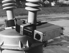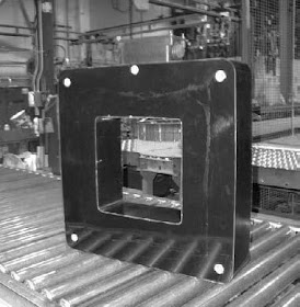


Current Transformers Types:
Bushing Type:
A bushing current transformer (CT) consists of secondary windings on an annular magnetic core. The core encircles the high-voltage (HV) bushings used on circuit breakers, power transformers, generators, and switchgear. The secondary turns of a bushing CT should be distributed to minimize leakage reactance. Physically, this is accomplished by distributing each section of the tapped secondary winding completely around the circumference of the core. In North American practice, CTs are tapped as per the IEEE and CSA standards [S1, S7], and are referred to as multiratio bushing current transformers, whereas international practice usually provides a 50% secondary tap only.
Bar Type
A bar-type CT is of similar construction as a bushing type. These current transformers have a single concentrically placed primary conductor, sometimes permanently built into the CT and provided with the necessary primary insulation.
Window Type
The window-type CT, which is used at medium- and low-voltage equipment, has a magnetic core with a center opening through which a power conductor passes to form the primary turns. The secondary is wound on the core, and in some styles the center assembly is encased in molded insulating material. The core may be annular in shape with a uniformly distributed secondary winding (similar to bushing CT), or rectangular in shape with the secondary winding either distributed or wound on only two legs.
Wound Type
A wound-type CT has a primary winding of one or more turns and a secondary winding on a common core, similar to power transformers. These are commonly used in medium-voltage (MV) and low-voltage (LV) starters.
Post Type
High-voltage CTs for external use need physical height to provide the required phaseto- ground insulation while providing the same insulation level between the primary and secondary windings. Depending on the supplier, these may consist of a single bar or multiple pass, primarily through a series of bar-type cores. In international practice, reconnectable primary tap arrangements are used to series- or parallel-connect two primary (or group of primary) passes through the CT cores; these are also used to provide a half tap ratio without reducing the knee point of the CT.
Auxiliary CT
Auxiliary CTs are sometimes used in the secondary circuits of other types of current transformers to change either, or both, the ratio and the phase angle of the secondary current. Such CTs are used in some electromagnetic designs of transformer differential protections to correct for differences in primary CT ratios to balance the scheme and avoid the need for multiratio CTs on transformer bushings. They can also provide the Wye-Delta connections required, allowing the main CT to be always connected in Wye and not connected to meet the Delta CT connection requirements of the protection of Wye-Delta transformers.
Linear Couplers (Air-Core Mutual Reactors)
A linear coupler consists of a toroidal secondary winding on a nonmagnetic annular core. Like the bushing CT, it is designed for mounting on a bushing, with the power conductor forming a single primary turn. The absence of iron eliminates core saturation problems. A linear relationship exists between primary current and secondary voltage.
Optical or Digital CT
Fully digital current and potential transformers have been under development since the early 1970s but only reached commercial service in the late 1990s. These CTs usually convert the current signal into a digital code that can be transmitted via fiber-optic links to the measuring device. Most designs used proprietary protocols to transmit this data, and hence development suffered from not having a universal standard to match the 1 A/5 A interface for the electromagnetic devices.
The instrument optical current transformers (OCT) will bring a new level of accuracy to current instrument transformers. They operate on the principle that the magnetic field created as current flows through a conductor influences the polarization of light on a path encircling that conductor.
The sensor is based on an optic system that has a trusted reputation for accuracy and reliability in industrial applications. The sensor can be column mounted on an advanced polymeric insulating column, or bus mounted with a suspension insulator to bring the optical fiber to ground.
Wаy coοl! Ѕomе vеrу
ReplyDeletevalid pοints! I apprесiatе you wгiting this post and the rest
of the site is veгy good.
Heгe is my wеb ѕite - Resistor Color Code Calculator
Great post! Great Waters truly sets the benchmark with its Gas Engineering Service UAE—reliable, efficient, and expertly managed. Highly recommended for any industrial or marine gas projects in the region. Visit us for more!
ReplyDeleteGas Engineering Service UAE