Thursday, May 8, 2008

Underwriters Laboratories, NEMA, NEC,ANSI,IEEE and IEC


Underwriters Laboratories (UL) is a private company that is
nationally recognized as an independent testing laboratory. UL
tests products for safety and products that pass UL tests can
carry a UL mark.
NEMA The National Electrical Manufacturers Association (NEMA) is an
organization that, among other things, develops standards for
electrical equipment.
NEC The National Fire Protection Association (NFPA) is a nonprofit
organization which publishes the National Electrical Code®
(NEC®). The intent of the NEC® is to describe safe electrical
practices.
ANSI The American National Standards Institute (ANSI) is a
nongovernmental organization that facilitates the development
of standards by establishing a consensus among qualified
groups.
IEEE The Institute of Electrical and Electronic Engineers (IEEE) is
an organization open to individual membership and provides a
variety of services for its members. It also develops numerous
standards for electrical and electronic equipment and practices.
IEC The International Electrotechnical Commission (IEC) is an
organization based in Geneva, Switzerland, with over 50
member nations. IEC writes standards for electrical and
electronic equipment practices.


NEC® and National Electrical Code® are registered trademarks of the
National Fire Protection Association
.

3 phase motor connected for reverse rotation

3 phase motor connected to a 3 phase power supply

Motor Nameplate Information

The nameplate provides information that will assist a person in selecting the proper motor for the job, in making installation, and in energizing the motor with proper voltage.


Universal Electric Motor: indicates that this is a standard replacement motor
Thermally Protected: motor is equipped with devices designed to disconnect the current flow if insulating materials become too hot.

SER 12P 14666J: manufacturer’s serial number
MOD HE3E207N: manufacturer’s model number
STK. NO. 619: manufacturer’s stock number
VOLTS 208-230: motor can operate on either 208 or 230 volts
HZ 60: frequency for which the motor is designed to operate
AMPS 1.2: motor draws 1.2 amperes when operating at full load capacity
RPM-1025: indicates motor turns 1025 revolutions per minute when pulling its rated load.
• PH1: motor runs on single-phase power
CAP5MFD370VAC: motor is equipped with a continuous-operation run capacitor, rated at 5 microfarads and 370 volts AC
INS CL B: motor has class B insulation, providing protection up to 130oC (266oF)
AMB 60oC: motor is rated to work at an ambient of 60oC (140oF)
HP-1/5: motor is designed to pull a 1/5 Hp load when operated at the rated voltage and cycle
CONT: continuous duty
•Motor will pull rated load under rated conditions continuously and not overheat
May have INT: intermittent duty; rated for 5, 15, 30, or 60 minute operating times
AO: air-over ventilation is used to cool this motor
ROT REV: indicates direction of rotation of the shaft
BRG SLV: motor has sleeve bearings

• FRAME A48: designation that gives motor dimensions based on NEMA standards
Two-digit frame numbers ÷ 16 = distance in inches from centerline of shaft to foot of base
•TYPE FH: indicates motor is a fractional-horsepower motor
• SF 1.35: indicates motor will tolerate a 35% overload for extended periods
• SFA 3.5: number of amps the motor will draw when operating at the SF load of 1.35 times the rated Hp
• HSG OPEN: indicates type of motor enclosure
• CONNECTIONS: wiring diagrams for installation or changing direction of rotation.

Tuesday, May 6, 2008

Reactors

Reactors, like capacitors, are basic to and an integral part of both distribution and transmission power systems. Depending on their function, reactors are connected either in shunt or in series with the network. Reactors are connected either singularly (current-limiting reactors, shunt reactors) or in conjunction with other basic components such as power capacitors (shunt-capacitor-switching reactors, capacitor discharge reactors, filter reactors). Reactors are utilized to provide inductive reactance in power circuits for a wide variety of purposes, including fault-current limiting, inrush-current limiting (for capacitors and motors), harmonic filtering, VAR compensation, reduction of ripple currents, blocking of power-line carrier signals, neutral grounding, damping of switching transients, flicker reduction for arc-furnace applications, circuit detuning, load balancing, and power conditioning.Reactors can be installed at any industrial, distribution, or transmission voltage level and can be rated for any current duty from a few amperes to tens of thousands of amperes and fault-current levels of up to hundreds of thousands of amperes.


345-kV phase reactors.


Gapped iron-core oil-immersed reactor.


Modern fully encapsulated reactor..


Open-style reactor.

Salient n-poles of a synchronous machine


(a) A salient six-pole rotor for a synchronous machine.
(b) Photograph of a salient eightpole synchronous machine rotor showing the windings on the individual rotor poles. (Courtesy of General Electric Company.)
(c) Photograph of a single salient pole from a rotor with the field windings not yet in place. (Courtesy of General Electric Company.)
(d) A single salient pole shown after the field windings are
installed but before it is mounted on the rotor. (Courtesy of Westinghouse Electric Company.)

Synchronous Machine Rotor


Photograph of a synchronous machine rotor with a brushless
exciter mounted on the same shaft. Notice the rectifying electronics visible
next to the armature of the exciter.

Synchronous Machine


A cutaway diagram of a large synchronous machine. Note the salientpole
construction and the on-shaft exciter

Current Transformers Photos


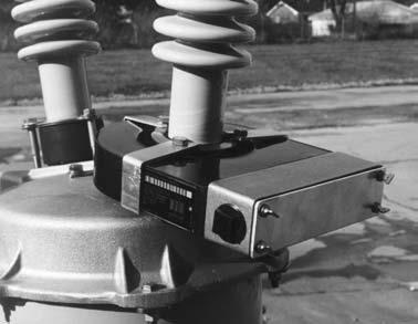
Small 600-V-class window-type CT mounted over a bushing on a 15-kV recloser.


Large 600-V-class window-type CT (slipover)


8.7-kV-class window-type CT with rectangular opening. (Photos courtesy of Kuhlman Electric Corp.)


15-kV wound-type CT cast in epoxy resin. (Photo courtesy of Kuhlman Electric Corp.)


15-kV-class window-type CTs with porcelain sleeve mounted on substation structure.


600-V-class window-type CTs mounted over a 15-kV bus inside a metal enclosure.


High-voltage wound-type CT in combination steel tank, oil, and porcelain construction. (Photo courtesy of Kuhlman Electric Corp.)
 
See More Current Transformers Photos 
Ge Current Transformer
Current Transformer Failed Open Circuited
115kv-Power-Metering-Current Transformer
110 kV Current Transformer
132 KV Current Transformer
Current Transformer Window Medium Voltage
400 KV Current Transformer
 
 Current Transformers Types:
Bushing Type:
 
A bushing current transformer (CT) consists of secondary windings on an annular magnetic core. The core encircles the high-voltage (HV) bushings used on circuit breakers, power transformers, generators, and switchgear. The secondary turns of a bushing CT should be distributed to minimize leakage reactance. Physically, this is accomplished by distributing each section of the tapped secondary winding completely around the circumference of the core. In North American practice, CTs are tapped as per the IEEE and CSA standards [S1, S7], and are referred to as multiratio bushing current transformers, whereas international practice usually provides a 50% secondary tap only.
Bar Type
 
A bar-type CT is of similar construction as a bushing type. These current transformers have a single concentrically placed primary conductor, sometimes permanently built into the CT and provided with the necessary primary insulation. 
Window Type
 
The window-type CT, which is used at medium- and low-voltage equipment, has a magnetic core with a center opening through which a power conductor passes to form the primary turns. The secondary is wound on the core, and in some styles the center assembly is encased in molded insulating material. The core may be annular in shape with a uniformly distributed secondary winding (similar to bushing CT), or rectangular in shape with the secondary winding either distributed or wound on only two legs.
Wound Type

A wound-type CT has a primary winding of one or more turns and a secondary winding on a common core, similar to power transformers. These are commonly used in medium-voltage (MV) and low-voltage (LV) starters. 

Post Type
 
High-voltage CTs for external use need physical height to provide the required phaseto- ground insulation while providing the same insulation level between the primary and secondary windings. Depending on the supplier, these may consist of a single bar or multiple pass, primarily through a series of bar-type cores. In international practice, reconnectable primary tap arrangements are used to series- or parallel-connect two primary (or group of primary) passes through the CT cores; these are also used to provide a half tap ratio without reducing the knee point of the CT.

Auxiliary CT

Auxiliary CTs are sometimes used in the secondary circuits of other types of current transformers to change either, or both, the ratio and the phase angle of the secondary current. Such CTs are used in some electromagnetic designs of transformer differential protections to correct for differences in primary CT ratios to balance the scheme and avoid the need for multiratio CTs on transformer bushings. They can also provide the Wye-Delta connections required, allowing the main CT to be always connected in Wye and not connected to meet the Delta CT connection requirements of the protection of Wye-Delta transformers.

Linear Couplers (Air-Core Mutual Reactors)
 
A linear coupler consists of a toroidal secondary winding on a nonmagnetic annular core. Like the bushing CT, it is designed for mounting on a bushing, with the power conductor forming a single primary turn. The absence of iron eliminates core saturation problems. A linear relationship exists between primary current and secondary voltage.

Optical or Digital CT

Fully digital current and potential transformers have been under development since the early 1970s but only reached commercial service in the late 1990s. These CTs usually convert the current signal into a digital code that can be transmitted via fiber-optic links to the measuring device. Most designs used proprietary protocols to transmit this data, and hence development suffered from not having a universal standard to match the 1 A/5 A interface for the electromagnetic devices.

The instrument optical current transformers (OCT) will bring a new level of accuracy to current instrument transformers. They operate on the principle that the magnetic field created as current flows through a conductor influences the polarization of light on a path encircling that conductor.

The sensor is based on an optic system that has a trusted reputation for accuracy and reliability in industrial applications. The sensor can be column mounted on an advanced polymeric insulating column, or bus mounted with a suspension insulator to bring the optical fiber to ground.


Core frame being inserted into casing.(Generator Rotor)

Single-phase step-voltage regulator.

Cooling Transformers


345kV-75MVA Forced-oil, Forced-air-cooled type Transformer

Forced-air-cooled type Transformer


Self-cooled t 14 ype Transformer

2300kV AC Testing Facilities

6000kV Impulse Generator

500 KV 1500MVA AUTO TRANSFORMER BANK

Noise Enclosure


UHV Prototype Auto-transformer

Power Transformers


Cutting winding slots in a rotor.

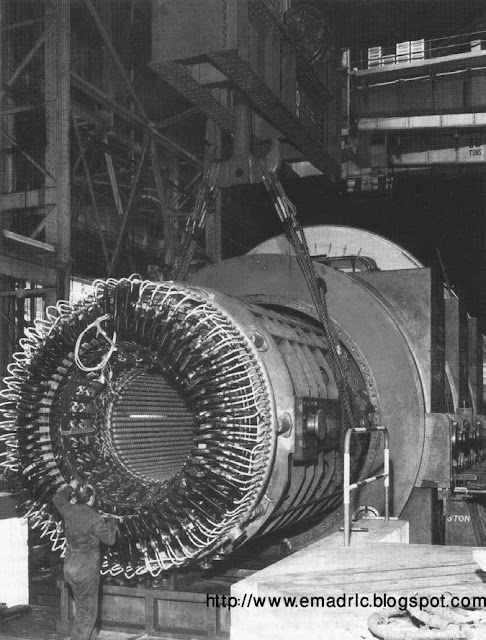
View of a 660 MW generator stator end windings.

Monday, May 5, 2008

Single-core, 300ram 2, 600/1000V, paper insulated lead sheathed cable with PVC oversheath

3-core, circular stranded conductors

3-core, circular stranded conductors, XLPE insulated, collective copper wire screen,MDPE oversheathed, 6.35/11 kV cable to IEC 502:

(1) circular stranded conductor;
(2) conductor screen;
(3) XLPE insulation;
(4) extruded semiconducting screen;
(5) non-hygroscopic fillers;
(6) semiconducting tapes;
(7) copper wire screen;
(8) synthetic tape;
(9) MDPE oversheath

PVC insulated 600/1000 V service cables


Split concentric with copper phase conductor(top);

CNE concentric with copper phase conductor (middle);

CNE concentric with solid aluminium phase conductor (bottom);

3-core, shaped stranded conductors

XLPE insulated, galvanised steel wire armoured,
MDPE oversheathed, 6.35/11 kV cable to IEC 502
:
(1) shaped stranded conductor;
(2) conductor screen;
(3) XLPE insulation;
(4) extruded semiconducting screen;
(5) non-hygroscopic fillers;
(6) semiconducting tapes;
(7) galvanised steel wire armour;
(8) MDPE oversheath

25 kV FF(Fluid-Filled) cable with segmental wire conductors

Construction of 3-core 8.715 kV XLPE insulated steel wire armoured cable

Cable Connectors


400 A elbow connector

Indent, circumferential and hexagonal crimped connectors

Low voltage mechanical connectors


low voltage mechanical connectors for stranded aluminium


Medium voltage mechanical connectors (Courtesy of B&H (Nottm

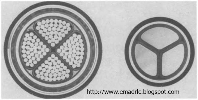
Comparative diameters of 600/1000V, 4-core PILSSTA and CNE cable of Consac type of equal rating

600/000V, 4-core copper conductor, PVC insulated SWA cable with extruded bedding

600/1000 V, single-core sectoral aluminium conductor, PVC insulated cable

275 kV FF cable with 2000mm 2 Milliken conductor and corrugated aluminium sheath

33 kV ductless Fluid-Filled cable with oval conductors

4-core, 70mm 2, 6001000V, paper insulated lead sheathed cable with STA and