The purpose of the seal oil system is to keep the compressed gas from entering the bearing assembly and escaping from the compressor to the atmosphere. The seal oil system may be a completely separate oil system, however in most cases it is apart of the compressor (main) lube oil system. The seal oil system can be considered as having three major levels of operation: Seals, Oil Supply, and Oil Return.
SEAL OIL SUPPLY SYSTEM:
The oil supply consists of a reservoir, pumps, filters, pressure control valve, cooler, level control valve and overhead tanks.

Typical Seal Oil Supply System
The oil used is held in an tank, which is purged to clear the tank of any gas at 3" w.c. vacuum by a jet blower attached to the reservoir. Also attached to the reservoir are two electric motor driven pumps that are selectable to run from the UCP (unit control panel), however, only onepump should be selected to run at any one time.
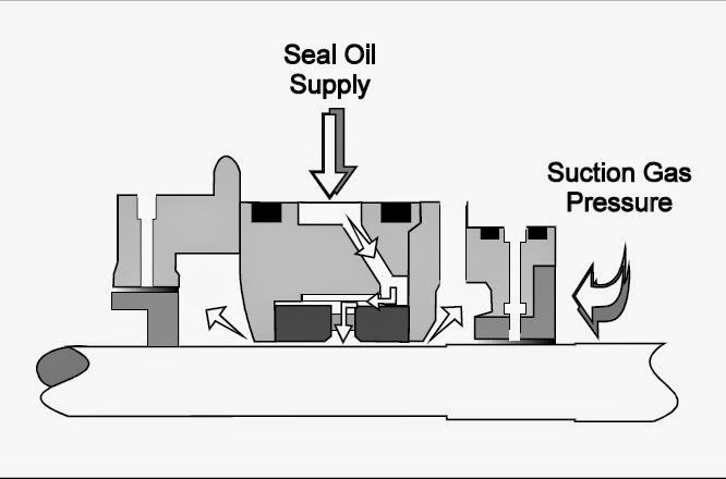
Now all that is needed is to control oil pressure to the seal. It is known that a greater oil pressure must be supplied to the seal than the gas pressure against the seal. So an overhead tank has been added to accomplish this task. The overhead tank is supplied with oil from the oil supply cavity of the oil film seal through the seal oil by-pass piping and with reference gas pressure piped to the top of the tank from the outboard side of the thrust balance piston.
In order to fill the tank with oil, the oil pressure must be greater than the gas pressure. By mounting the tank above the compressor, the oil supply pressure to the seals must then be even greater to overcome the added gravitational force of oil in the by-pass line and tank.
To summarize, the supply of seal oil should be equal to the gas reference pressure plus the head of oil maintained in the overhead tank serving each set of seals in each compressor. Seal differential is the head of oil maintained in the tank against the seal.
To summarize, the supply of seal oil should be equal to the gas reference pressure plus the head of oil maintained in the overhead tank serving each set of seals in each compressor. Seal differential is the head of oil maintained in the tank against the seal.
COMPONENT DESCRIPTION:
Seals:
Cooper-BessemerÒ Compressors use the labyrinth and oil film type seals working in combination within a cartridge to seal against gas leakage during operation whenever gas is present in the compressor. Each end of the compressor is equipped with a seal cartridge.
Seals:
Cooper-BessemerÒ Compressors use the labyrinth and oil film type seals working in combination within a cartridge to seal against gas leakage during operation whenever gas is present in the compressor. Each end of the compressor is equipped with a seal cartridge.

Cutaway of a typical Barrel Compressor

Typical Labyrinth Seal
LABYRINTH SEAL:
A labyrinth seal has a series of teeth with a close clearance to the shaft (See above illustration). Labyrinth seal work similar to an orifice in a pipe.
As the high pressure gas passes through the first tooth the pressure is decreased to approximately half its original pressure and velocity is increased. The gas then enters the chamber before the second tooth. A natural turbulence is created, which reduces the velocity allowing the gas to expand in the cavity between labyrinth teeth. This process is repeated for each tooth of the labyrinth. The result is a large reduction in gas pressure across the seal.
OIL FILM SEAL CARTRIDGE:
The oil film seal is made up of two free floating rings which are machined with a very small clearance around the shaft (See following illustration). Clean high pressure oil is squeezed between the rings and shaft, and out both directions. As long as the oil pressure is greater then the gas pressure, the seal will not allow gas to escape.

Typical Oil Film Seal
The seals are bench assembled as a cartridge. The seal cartridge is put onto the shaft and in to the compressor at each end. Because the oil film seal requires an oil supply and drainage, the casing and cartridge housing are machined and drilled with matching annular ports, or, holes (See above illustration). These annular ports are sealed from one another by Orings assembled onto the O.D. of the cartridge.
SEAL OIL Cartridge SUPPLY:
Seal oil is supplied and flows between the seal rings (See following
illustration). The majority of oil will flow to the low pressure side of the seal cartridge. The high pressure side of the seal cartridge is where the gas and oil come into contact with one another. The labyrinth seal on the high pressure side of the seal cartridge reduces the higher gas pressure. This reduced gas pressure is sealed from the system by the high pressure oil passing through the gas side seal ring. Oil supply is maintained at a greater pressure between the seal rings than compressor suction pressure to insure a positive seal and safe operation at all times.
Typical Seal Oil Supply Flow
SEAL OIL RETURN:
SEAL OIL CARTRIDGE RETURN OIL FLOW:
The oil flowing to the bearing side (low pressure) of the seal cartridge is not contaminated with gas, and returns directly to the reservoir. The oil flowing to the process side (high pressure) of the seal cartridge is contaminated with gas and goes to the degasser system.
The return of oil from each seal is provided by two ports off the
compressor housing. A 1-1/2" pipe is connected to the outboard side of the oil film seal. This uncontaminated oil is returned to the reservoir. This is where the majority of oil will flow. On the inboard side of the oil film seal, the oil comes in contact with a small amount of gas that has leaked past the labyrinth seal. This contaminated oil must be treated specially before returning it to the reservoir.
compressor housing. A 1-1/2" pipe is connected to the outboard side of the oil film seal. This uncontaminated oil is returned to the reservoir. This is where the majority of oil will flow. On the inboard side of the oil film seal, the oil comes in contact with a small amount of gas that has leaked past the labyrinth seal. This contaminated oil must be treated specially before returning it to the reservoir.
The first step of this treatment is the trap system. The oil is sent from the compressor to the trap through a 1" pipe.
Provided the pressure in the pipe is over 5 psig, it will enter the trap. If less than 5 psig, it will pass through an excessive flow valve and directly to the degasser tank for gas removal. The excessive flow valve is used to keep the seal from flooding when the compressor case is not pressurized.
Provided the pressure in the pipe is over 5 psig, it will enter the trap. If less than 5 psig, it will pass through an excessive flow valve and directly to the degasser tank for gas removal. The excessive flow valve is used to keep the seal from flooding when the compressor case is not pressurized.

Trap System
The trap is a vessel that is level controlled and ported at the top for gas venting and bottom for oil drainage. The oil enters the trap and is given some time to allow the gas to separate from the oil, until the level of oil becomes too high and is drained.
This process is controlled by a level controller that regulates 100 psig air supply to a 3-15 psig control signal. This control signal is sent to a dump valve that is adjusted to open at 12 psig and to a high trap level alarm switch. The oil drains through the dump valve and into a common pipe with the other trap drains to the degasser system. The vented gases from the traps are passed through a final demister before going to atmosphere.
DEGASSER TANK:

The degasser tank is the second stage of removing gas from the oil. It is a tank with baffles of various heights. The contaminated oil enters into the first chamber and is heated. This heating thins the oil and allows the gas to separate faster and easier. The element used for heating the oil is controlled through the Motor Control Center (MCC), which will control the temperature using an adjustable temperature switch. The temperature is also monitored by the UCP that will generate an alarm for low or high temperatures. Should the oil level in this chamber drop below 12 inches, a level switch will disconnect the power to the heater. The oil will pass over the other baffles that will agitate the oil and release all the gas. The final chamber oil level will be monitored by a level switch that will generate a low level alarm at the UCP. Once in the final chamber, the oil will be drained back to the reservoir for re-use.
The degasser tank also requires a purge of gas that is supplied off the suction header through a separator and filter. This purging gas keeps the gas content in the tank at a high
enough level so it is not explosive. The purge gas supply is controlled and monitored by the UCP through a solenoid and pressure switch.
enough level so it is not explosive. The purge gas supply is controlled and monitored by the UCP through a solenoid and pressure switch.
BALANCING:
SEAL BALANCING:
The gas pressure in on the inboard side of the seal cartridges is equalized by an interconnecting pipe called the seal balance line. This allows for one seal system to supply both end seals during operation rather than two separate systems, one serving each seal.
A gas reference line is piped from the thrust balance port on the discharge end of the compressor to a supply of seal oil maintained in an overhead tank approximately 5-6 meters above the horizontal centerline of each compressor. While the unit is running and the compressor case is pressurized, the reference gas represents the pressure used to seal against.

Typical Seal Balance Piping
THRUST BALANCE:
Suction gas pressure is piped from the suction of the compressor to a port behind the thrust balance piston by the thrust balance piping. The thrust balance line is used in conjunction with the thrust balance piston and labyrinth to reduce excessive forces of the thrust toward suction that develops during normal operation. The gas pressure behind the thrust balance piston will be suction pressure plus a small amount of gas leakage across the balance piston from the last stage impeller. Under any circumstances, the pressure behind the thrust balance piston represents the pressure necessary to seal against.

Typical Thrust Balance Piping
OPERATION:
Should one of the pumps fail during operation, A pressure switch would operate and show a seal oil supply low alarm and start the other pump. Should the filter become plugged, a differential pressure switch will send a signal to the UCP and an alarm will be sounded. The filter should be selected to the spare and the dirty one cleaned or replaced.
Now that the tank is elevated and has this added gas pressure, the oil within the tank will supply emergency oil to the seals for a period of time should the pumps shut off. Now what is needed during operation is a controller to maintain the correct oil level in the overhead tank. This is done by a Fisher pneumatic level controller that will regulate a 100 psig air supply to 3-15 psig depending on the level in the tank. This signal is then connected to a controller valve that will regulate the oil pressure going to seals. The controller must be set to maintain the recommended level in the overhead tank serving each compressor. This is done by loosening the spring to fill the tank higher or tightening the spring for a lower level. There is also added a main regulating valve which may be adjusted by tightening the spring to raise the levels of both tanks or loosening to decrease levels.
Startup of the Coberra Gas Turbine Unit is initiated by startup of the electric motor driving selected L.O. pump to deliver oil to the compressor overhead seal oil rundown tank via the seal boost pump, this fills the system and ensures proper supply of oil to the machinery. During this phase of startup, the lube oil rundown tank serving the disc end journal bearing on an emergency shutdown involving loss of power, is also filled.
Establishing correct L.O. pressure as well as seal and lube oil tank levels
is required for the startup control sequence to progress. The supply must be sufficient to ensure against the escape of any gas within the compressor, maintaining a positive sealing of the gas within the casing during operation or shutdown if the cases remained pressurized.
is required for the startup control sequence to progress. The supply must be sufficient to ensure against the escape of any gas within the compressor, maintaining a positive sealing of the gas within the casing during operation or shutdown if the cases remained pressurized.
During normal operation only one of the seal oil pumps is on-line. The other pump, depending upon selection, functions as a back-up pump should alarms occur.
Once the system has been proven during start the following will occur:
Once the system has been proven during start the following will occur:
1. Arm the Lube and Seal Oil Low & High Level and Pressure alarm and shutdowns in the system.
2. The Unit is ready for further sequencing as follows:
· System ready for compressor case purge and pressurization cycles
· Unit valve sequencing can begin.
· When purging and pressurizing of the compressor case is
completed and valves are in correct position it is they permissible to start the gas generator.
13 comments:
Good to know the role of seal oil system in gas compression. All the diagrams in the content are very helpful to understand everything. Thanks for sharing this with us!
Nice post thanks for sharing.
Trickle Varnish Impregnating Machine is suitable for pre-heating, trickling and post heating of stators. The machine is simple and compact in design. It is easy for operation and maintenance.
Batch Type Trickle Impregnating Machine
Varnishing Machines
Index Type Trickle Impregnating Machine
Vacuum / Pressure Impregnation Plants Manufacturer
Vacuum / Pressure Impregnation Plants supplier
Vacuum / Pressure Impregnation Plants exporter
Thanks For sharing this wonderful blog.This is very easy to understand.All the diagrams in the content are very helpful to understand everything.Thanx for sharing with us.
i have also one post releated with this.
AR Engineering for manufacturing of transformer oil filtration machines. Since then AR Engineering has developed different types of Insulating Oil upgrading systems suitable for in-house and onsite operation.
for more details please visit:http:http://varnishingmachine.com/
oil filteration plants
Trickle Impregnation technique exporter in pune
Industrial Oil Purification Systems manufacturer in india
Index Type Trickle Impregnating Machine exporter in pune
Batch Type Trickle Impregnating Machines exporter in pune
Vacuum Pressure Impregnation Plants Manufacturer Exporter
Transformer Oil Filtration Plants exporter in pune
Nice post,Thanx for posting
AR Emgineering is one of the best manufacturing of transformer oil filtration machine in Pune.
Batch Type Trickle Impregnating Machine manufacturer in pune
Index Type Trickle Impregnating Machine manufacturer in pune
Vacuum Impregnation Plants
industrial oil filtration plant
Transformer Oil Filtration Plants manufacturer in pune
Trickle Impregnation Technique manufacturer in pune
Varnishing Machines suppliers in pune
oil filtration machines,oil purification
Transformer Oil Filtration manufacturer in india
Transformer Oil Filtration Plants exporter in india
Thanks for Shearing This Post
AR Engineering is a manufacturing of transformer oil filtration machines. The plants are suitable for Transformer & Capacitor Manufacturers,Oil filtration service providers etc.
High Vacuum Transformer Oil Filtration and Dehydration Plants
Varnishing Machines :-
Trickle Impregnation Technique
Batch Type Trickle Impregnating Machine
Index Type Trickle Impregnating Machine
Vacuum Impregnation Plants / Pressure Impregnation Plants
Industrial Oil Purification Systems
Oil from Gulf EP offers outstanding lubrication performance and protection against shock loading and wear as well as resistance to high temperature deposit formation. best oil for cars
Thanks for sharing such an informative post.
Get the best industrial oil suppliers at best prices.thank you
Nice articles and your information valuable and good articles thank for the sharing information Transformer Oil Filtration Plant
Discover how our filtration plant solutions can benefit your business. We offer a range of solutions for industrial clients, including our high vacuum-based transformer oil filtration plant
Great post! Great Waters delivers exceptional Detailed Engineering Design Services UAE, ensuring accuracy, innovation, and efficiency. Their expertise makes them a trusted partner for complex marine and energy projects. Visit us for more!
Detailed Engineering Design Services UAE
Great overview of filling machine technology. Efficient and accurate filling solutions are very important for industries like lubricants, especially in a Lube Oil Blending Plantwhere precision and automation help improve productivity and reduce wastage.
Great insights on the Lube Blending Plant industry. Modern lube oil blending plants help improve production efficiency, quality control, and lubricant performance for industrial applications.
Post a Comment