Showing posts with label Circuit Breakers. Show all posts

Wednesday, March 25, 2015

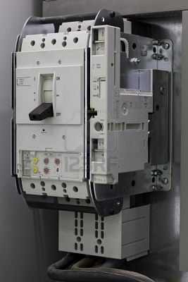
Low-voltage draw-out power circuit breaker


Low-voltage draw-out power circuit breaker. 

(a) Front view showing name plate of CH-DSLII
and protective trip devices, (b) side view showing operating mechanism, and
 (c) back view showing disconnect stubs and fi nger cluster, and CLF fuses.

Monday, March 16, 2015

Medium voltage power vacuum circuit breaker

Medium voltage power vacuum circuit breaker. (a) Side view showing vacuum bottles and(b) back view showing primary disconnect fingers.

Tuesday, July 31, 2012

Miniature circuit breakers

The miniature circuit breaker (mcb) has a contact system and means of arc quenching, a mechanism and tripping and protection system to open the circuit breaker under fault conditions.

Most mcbs are of single-pole construction for use in single-phase circuits. The complete working system is housed within a plastic moulding, typical external appearance being shown in Fig. (1). A section showing the principal parts of the mcb is shown in Fig. (2). The contact system comprises a fixed and a moving contact, and attached to each is a contact tip which provides a low-resilience contact junction to resist welding.

 Fig (1) Miniature circuit breaker, external view

 Fig (2) Principal parts of a miniature circuit breaker  ABB


Modern mcbs are fitted with arc chutes consisting of metal plates which are held in position by insulating material. The arc chute does not necessarily surround the contact; in some designs arc runners are provided to pull the arc into the arc chute.


The tripping mechanism usually consists of a thermal-magnetic arrangement. The thermal action is provided by a bimetal with, in some cases, a heater. For ratings in the range 6–63A the bimetal forms part of the current path, the heat generated within the bimetal itself being sufficient to cause deflection. The deflection is then used to activate the tripping mechanism. The characteristics of the bimetal are chosen to provide particular delays under certain overload or fault currents according to the required time–current characteristic. A high-resistance bimetal is used for low-current devices and a lower resistance bimetal for high-current devices. In very low-current mcbs a heater may be incorporated around the bimetal in order to generate sufficient heat to deflect it.

 High breaking capacity mini circuit breaker 32A
             High breaking capacity mini circuit breaker 63A
 
The magnetic tripping element usually consists of a coil which is wrapped around a tube, there being a spring-loaded slug within the tube. Movement of the slug operates the tripping mechanism to open the mcb. It can also be used to assist in opening the contacts by locating the coil close to the moving contact. 

When a fault current flows, the high magnetic field generated by the coil overcomes the spring force holding the slug in position; the slug then moves to actuate the tripping mechanism and forces the contacts apart by striking the moving contact arm. For low mcb ratings the coil is formed from thin wire with many turns; for higher ratings the wire is thicker, with fewer turns.

 The magnetic trip is set by the manufacturer according to the required characteristics. These characteristics are defined in the standard and form ‘types’ which are shown in Table 1.

MCBs are designed and tested according to the requirements of IEC 898.


Table (1) Magnetic trip settings for mcbs

Friday, July 27, 2012

Circuit Breaker Types

Circuit breakers can be classified by the arc-quenching media they use. The following is a brief listing of the different types, in the order of their historical development.

Air-Magnetic Air Quenching

These types of breakers date back to the early 1900s and were used in the medium voltage range to about 15 kV. They interrupt the current by drawing the arc into and extending it in a magnetic field and creating an increased air flow to extinguish it.
This type of breaker was used in industrial and power installations to about the early1960s. A well-known example is the GE or Westinghouse Magna-blast breaker, stillin service in a number of installations. They are no longer readily available. 


Oil Circuit Breakers

Oil circuit breakers were the dominant type of breakers used in both the medium- and high-voltage range up to 345 kV until the early 1960s in the North American and British practice. The arc quenching is by the turbulent flow of oil originally by the effect of the arc and later by some improved design of the construction of
the chamber surrounding the contacts. These breakers are distinguished by the relatively large amount of oil required for the effective and efficient arc interruption.


Oil circuit breakers are used to switch circuits and equipment in and out of a system in a substation. They are oil filled to provide cooling and to prevent arcing when the switch is activated.


Air-Blast Breakers

Air-blast breakers were used in Europe from the early 1930s in both the medium- and high-voltage range, but they were used in North America only from the late 1950s, and because of the advent of SF6 gas circuit breakers, only for a relatively short period of time. All air-blast breakers are based on the principle of high-pressure air, on the order of 200 psi, forced through a nozzle and passed at high speed across the arc, partly to lengthen the arc and partly to carry away the arc/plasma product from in between the contacts. To this end, a central high-pressure storage or high-pressure individual breaker air storage is used.


Air-blast breakers have been manufactured for voltages up to 800 kV, and were used for the development of 500 kV systems. Because of their good functionality at low temperatures, they were frequently used in the northern latitudes.


SF6 Gas Circuit Breakers

SF6 breakers  were developed in the 1960s and quickly became the preferred choice for wide areas of medium- and high-voltage applications. These breakers utilize SF6 gas for the extinction of arc, having dielectric properties superior to that of air, leading to a much more economical design in the construction and dimensions of the breaker. The voltage rating for a single interrupter head is mostly limited to 245 kV, hence more than one head in series is used for higher voltages. The initial development of the SF6 breaker was the so-called double-pressure breaker mimicking
the operating principle of an air-blast breaker.


This construction was replaced by the so-called puffer breakers. The SF6 gas is passed to and held in the contact chamber at a gas pressure of about 50 to 70 psi (three to five times atmospheric pressure). Upon contact parting, a piston compresses the gas and blasts it through the arc, returning it to the closed SF6 circulation loop in the breaker. SF6 breakers are the breaker type predominantly used in the HV and EHV voltage range, and widely used for medium voltages.

Vacuum Circuit Breakers

Vacuum breakers  utilize the superior dielectric nature of the vacuum for arc extinction. They consist of a vacuum- tight “bottle” housing the fixed and moving Cu or Cr contacts. The contact movement and separation is very small, on the order of millimeters rather than centimeters, which makes the operation of these breakers and their ability of arc extinction very fast. Some problems associated with this phenomenon will be discussed later.
Vacuum breakers for fault-current interrupting capabilities similar to SF6 breakers are available in the medium voltage range up to about 35 kV and at 25-kV single phase (50-kV equivalent) as dual bottle assemblies for electric traction. Vacuum switches as load-break switches consisting of a series of assembly of vacuum bottles are available up to 245 kV.


Sunday, July 8, 2012

Combination motor starter with circuit breakers,disconnect switch, and control transformer.(Courtesy Square D Company.)

Combination motor starter with circuit breakers, disconnect switch, and control transformer. (Shown inside module used for insertion into a motor control center.)
(Courtesy Square D Company.)

What is a circuit breaker and how does it function?


A circuit breaker is an overcurrent protection device. It opens and closes a circuit automatically on a predetermined overcurrent. Subsequently, the circuit closes automatically or manually.


A circuit breaker is an overcurrent protection device. It opens and closes a circuit automatically at a predetermined overcurrent. When the circuit breaker is applied correctly within its rating, opening and closing the circuit breaker does not damage it. It is easy to reactivate the circuit breaker immediately after a overload has occurred. The circuit breaker is simply reset after the fault is corrected.

Different types of circuit breakers
We distinguish between two kinds of circuit breakers:
Thermal and magnetic circuit breakers.


Thermal circuit breakers
Thermal circuit breakers are the most reliable and cost effective type of protection device that exists and are well-suited for motors. They can withstand high-level current waves, which arise from motor starts and they protect the motor against failure e.g. locked rotor.

Magnetic circuit breakers
Magnetic circuit breakers are precise, reliable and cost-effective. The magnetic circuit breaker is stable temperature-wise, meaning that it is rarely affected by changes in the ambient temperature.
Compared to thermal circuit breakers, magnetic circuit breakers offer a more precise trip time. The illustration on your right-hand side shows the characteristics of the two types of circuit breakers.


Circuit breaker rating

Circuit breakers are rated according to the level of fault current they interrupt. So, when you select a circuit breaker, always choose one that can sustain the largest potential short-circuit current, which is likely to occur in the application.


Tuesday, July 3, 2012

General Electric Vacuum Distribution Circuit Breaker

High voltage circuit breakers with vacuum insulation
for use in electrical power distribution substations.

General Electric:15.5 KV/1200 A