TRANSFORMERS - GENERAL
VA Rating
Every transformer has a maximum output current that it can deliver at its standard output voltage. This VA rating (KVA or MVA for large power transformers) is dependent on the ambient temperature or cooling provided. Exceeding the VA rating will cause over-heating of the core and windings and subsequent damage.
Cooling
Cooling requirements for the VA rating(s) are usually listed on the
nameplate along with the ambient operating temperature. Oil filled
transformers, will include the type of cooling at which the full rated
load can be delivered. A typical 1000kVA oil filled transformer that
has radiators to allow natural air cooling of the oil, would be listed as:
Transformer Rating: 1000 KVA 550C ONAN, which stands for the
capability to supply 1000KVA with a temperature rise of 550C with
normal oil circulation (no fans or pumps).
The various abbreviations that you will find for transformer cooling
are:
• ONAN cooling. ONAN is an abbreviation for Oil Natural
(thermo-syphon) circulation with Air Naturally circulated for
cooling.
• ONAF abbreviation denotes that the transformer has provision
for Oil Natural Air Forced cooling. Forced air-cooling would
allow the rating to be increased by a small amount.
• OFAF stands for forced (pumped) oil circulation and forced
(fan) air-cooled radiators.
• OFW - The main transformers at large generating stations are
OFW types with oil forced cooling, where the oil is, in turn,
cooled by water.
For large power transformers, there are usually multiple ratings
depending on the type of cooling applied. Typical cooling
requirements for transformers equipped with circulating oil pumps and
air-cooled radiators are usually listed as:
450/600/750 MVA 650C
ONAN/ONAF/OFAF
This rating, with a 650C ambient temperature rise, would be:
• 450 MVA with normal oil circulation, no fans or oil pumps on.
• 600 MVA with normal oil circulation, fans on.
• 750 MVA with both fans and oil pumps on.
Frequency
All transformers are designed for the optimum flux linkages and
lowest heating and power loss at a certain frequency. An induced
voltage is created by an alternating magnetic field. At higher-thanrated
frequency, there is excessive core loss due to lower efficiency in
flux linkages. At lower-than-rated frequency, there is excessive
winding loss due to decrease of flux linkages.
Transformers are basically inductors:
• Increasing frequency increases impedance and lowers current
(less flux).
• Decreasing frequency decreases impedance and increases
winding current (more heat).
Voltage
The available winding insulation is the governing factor for the voltage rating on the transformer. As well as the rated operating voltage, the rated transient (spike) voltage that the transformer can withstand is usually included. This is listed as the impulse level or BIL.
Phase
Single Phase on a Common Iron Core
Quite often, large three-phase power transformers are installed by
constructing three single-phase transformers and tying their input or output windings together. Such as the case for most main power output transformers that transform the generator power from high current, isolated phase buses to high voltage electrical system. Construction of a single three-phase transformer would be out of the question.
Single Phase on a Common Iron Core
Most power transformers encountered are of this construction for size and cost efficiency.
Windings
Separate windings (standard).
Fig 1 Two Winding Transformer
Auto-transformer.
The autotransformer has the same ratios (turns, voltage and current) as a transformer with two separate windings. However, the output is tapped off a portion of the single winding. This configuration yields itself to creating variable tapped output voltages, as we will discuss later.
Connections
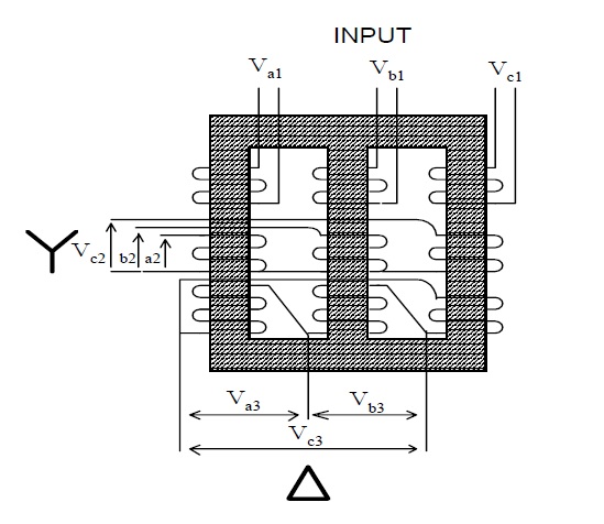
The common transformer connections are single phase, 3 phase star, 3 phase delta, or zigzag. (The latter connection is used explicitly in grounding transformers and will not be discussed in this course.)
Figure 3 below is an example of the connections for a three-phase
transformer. Individual three-phase inputs are transformed into two
separate outputs - one star or “wye”, the other delta.
The primary and secondary windings on most three-phase
transformers are connected in either star or delta formation.
The star point, (see Figure 3) of a star winding is connected to ground NotesN otes:
and this ensures the line terminals have equal and balanced voltages to ground. The delta winding, because it does not have a common (star) point, is not connected to ground at the transformer.
Taps
Winding taps are provided in transformers to adjust the turns ratio
between input and output and, hence, adjust the output voltage.
• Off-load taps are for use in transformers that rarely require
output voltage adjustments. For example, a generator
main-power output transformer.
• On-load taps that require frequent operations as customer or
system load fluctuates during the day.
Engineering 4all, Practical Engineering, Free Learning Source, By Photos You Can Learn What you are studying.
Pages
- Home
- Industrial Instrumentation
- Manuals Requests:
- DNA Testing
- What is Electrical Engineering?
- How Satellite TV Works?
- Website Hosting?
- What is cord blood?
- What is Data Recovery?
- Online Engineering Education
- General Electric Turbine
- Nature Photos
- Electrical Glossary
- Electrical Engineering Overview
- Electrical Courses and Lectures
- Valves
- Fundamental of Electricity 1
- Fundamentals Of Electricity 2
- Fundamentals Of Electricity 3
- Electrical Distribution Equipments Part A
- Electrical Distribution Equipments Part B
- Electric Motors Course
- ABB


No comments:
Post a Comment